All led grow lights are from ledhydroponics.co.uk
all grows are from ledhydroponics customers.
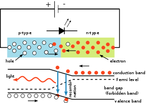
A light-emitting diode (LED) is a two-lead semiconductor light source. It is a pn-junction diode, which emits light when activated.[4] When a suitable voltage is applied to the leads, electrons are able to recombine with electron holes within the device, releasing energy in the form of photons. This effect is called electroluminescence, and the color of the light (corresponding to the energy of the photon) is determined by the energy band gap of the semiconductor.
An LED is often small in area (less than 1 mm2) and integrated optical components may be used to shape its radiation pattern.[5]
Appearing as practical electronic components in 1962,[6] the earliest LEDs emitted low-intensity infrared light. Infrared LEDs are still frequently used as transmitting elements in remote-control circuits, such as those in remote controls for a wide variety of consumer electronics. The first visible-light LEDs were also of low intensity, and limited to red. Modern LEDs are available across the visible, ultraviolet, and infrared wavelengths, with very high brightness.
Early LEDs were often used as indicator lamps for electronic devices, replacing small incandescent bulbs. They were soon packaged into numeric readouts in the form of seven-segment displays, and were commonly seen in digital clocks.
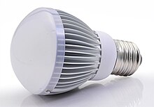
Recent developments in LEDs permit them to be used in environmental and task lighting. LEDs have many advantages over incandescent light sources including lower energy consumption, longer lifetime, improved physical robustness, smaller size, and faster switching. Light-emitting diodes are now used in applications as diverse as aviation lighting, automotive headlamps, advertising, general lighting, traffic signals, and camera flashes. However, LEDs powerful enough for room lighting are still relatively expensive, and require more precise current and heat management than compact fluorescent lamp sources of comparable output.
LEDs have allowed new text, video displays, and sensors to be developed, while their high switching rates are also useful in advanced communications technology.
| Light-emitting diode | |
|---|---|
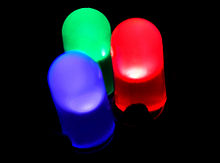
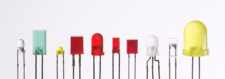
Blue, pure green, and red LEDs in 5 mm diffused cases
|
|
| Type | Passive, optoelectronic |
| Working principle | Electroluminescence |
| Invented | Oleg Losev (1927)[1] James R. Biard (1961)[2] Nick Holonyak (1962)[3] |
| First production | October 1962 |
| Pin configuration | anode and cathode |
| Electronic symbol | |

History
Discoveries and early devices
Electroluminescence as a phenomenon was discovered in 1907 by the British experimenter H. J. Round of Marconi Labs, using a crystal of silicon carbide and a cat’s-whisker detector.[7][8] Soviet inventor Oleg Losev reported creation of the first LED in 1927.[9] His research was distributed in Soviet, German and British scientific journals, but no practical use was made of the discovery for several decades.[10][11] Kurt Lehovec, Carl Accardo and Edward Jamgochian, explained these first light-emitting diodes in 1951 using an apparatus employing SiC crystals with a current source of battery or pulse generator and with a comparison to a variant, pure, crystal in 1953.[12][13]
Rubin Braunstein[14] of the Radio Corporation of America reported on infrared emission from gallium arsenide (GaAs) and other semiconductor alloys in 1955.[15] Braunstein observed infrared emission generated by simple diode structures using gallium antimonide (GaSb), GaAs, indium phosphide (InP), and silicon-germanium (SiGe) alloys at room temperature and at 77 kelvins.
In 1957, Braunstein further demonstrated that the rudimentary devices could be used for non-radio communication across a short distance. As noted by Kroemer[16] Braunstein”.. had set up a simple optical communications link: Music emerging from a record player was used via suitable electronics to modulate the forward current of a GaAs diode. The emitted light was detected by a PbS diode some distance away. This signal was fed into an audio amplifier, and played back by a loudspeaker. Intercepting the beam stopped the music. We had a great deal of fun playing with this setup.” This setup presaged the use of LEDs for optical communication applications.

In the fall of 1965, while working at Texas Instruments Inc. in Dallas, TX, James R. Biard and Gary Pittman found that gallium arsenide (GaAs) emitted infrared light when electric current was applied. On August 8, 1962, Biard and Pittman filed a patent titled “Semiconductor Radiant Diode” based on their findings, which described a zinc diffused p–n junction LED with a spaced cathode contact to allow for efficient emission of infrared light under forward bias.
After establishing the priority of their work based on engineering notebooks predating submissions from G.E. Labs, RCA Research Labs, IBM Research Labs, Bell Labs, and Lincoln Lab at MIT, the U.S. patent office issued the two inventors the patent for the GaAs infrared (IR) light-emitting diode (U.S. Patent US3293513), the first practical LED.[18] Immediately after filing the patent, Texas Instruments began a project to manufacture infrared diodes. In October 1962, they announced the first LED commercial product (the SNX-100), which employed a pure GaAs crystal to emit a 900 nm light output.
The first visible-spectrum (red) LED was developed in 1962 by Nick Holonyak, Jr., while working at General Electric Company.[6] Holonyak first reported his LED in the journal Applied Physics Letters on the December 1, 1962.[19][20] M. George Craford,[21] a former graduate student of Holonyak, invented the first yellow LED and improved the brightness of red and red-orange LEDs by a factor of ten in 1972.[22] In 1976, T. P. Pearsall created the first high-brightness, high-efficiency LEDs for optical fiber telecommunications by inventing new semiconductor materials specifically adapted to optical fiber transmission wavelengths.[23]
Initial commercial development
The first commercial LEDs were commonly used as replacements for incandescent and neon indicator lamps, and in seven-segment displays,[24] first in expensive equipment such as laboratory and electronics test equipment, then later in such appliances as TVs, radios, telephones, calculators, as well as watches (see list of signal uses). Until 1968, visible and infrared LEDs were extremely costly, in the order of US$200 per unit, and so had little practical use.[25] The Monsanto Company was the first organization to mass-produce visible LEDs, using gallium arsenide phosphide (GaAsP) in 1968 to produce red LEDs suitable for indicators.[25] Hewlett Packard (HP) introduced LEDs in 1968, initially using GaAsP supplied by Monsanto. These red LEDs were bright enough only for use as indicators, as the light output was not enough to illuminate an area. Readouts in calculators were so small that plastic lenses were built over each digit to make them legible. Later, other colors became widely available and appeared in appliances and equipment. In the 1970s commercially successful LED devices at less than five cents each were produced by Fairchild Optoelectronics. These devices employed compound semiconductor chips fabricated with the planar process invented by Dr. Jean Hoerni at Fairchild Semiconductor.[26][27] The combination of planar processing for chip fabrication and innovative packaging methods enabled the team at Fairchild led by optoelectronics pioneer Thomas Brandt to achieve the needed cost reductions.[28] These methods continue to be used by LED producers.[29]

Most LEDs were made in the very common 5 mm T1¾ and 3 mm T1 packages, but with rising power output, it has grown increasingly necessary to shed excess heat to maintain reliability,[30] so more complex packages have been adapted for efficient heat dissipation. Packages for state-of-the-art high-power LEDs bear little resemblance to early LEDs.
The blue and white LED

The first high-brightness blue LED was demonstrated by Shuji Nakamura of Nichia Corporation in 1994 and was based on InGaN.[31] In parallel, Isamu Akasaki and Hiroshi Amano in Nagoya were working on developing the important GaN nucleation on sapphire substrates and the demonstration of p-type doping of GaN. Nakamura, Akasaki and Amano were awarded the Nobel prize in physics for their work.[32] In 1995, Alberto Barbieri at the Cardiff University Laboratory (GB) investigated the efficiency and reliability of high-brightness LEDs and demonstrated a “transparent contact” LED using indium tin oxide (ITO) on (AlGaInP/GaAs). The existence of blue LEDs and high-efficiency LEDs quickly led to the development of the first white LED, which employed a Y
3Al
5O
12:Ce, or “YAG”, phosphor coating to mix down-converted yellow light with blue to produce light that appears white.
In 2001[33] and 2002,[34] processes for growing gallium nitride (GaN) LEDs on silicon were successfully demonstrated. In January 2012, Osram demonstrated high-power InGaN LEDs grown on silicon substrates commercially.[35] It has been speculated that the use of six-inch silicon wafers instead of two-inch sapphire wafers and epitaxy manufacturing processes could reduce production costs by up to 90%.[36]
Illumination breakthrough
The invention of the blue LED made possible a simple and effective way to generate white light. By coating a blue LED with a phosphor material a portion of the blue light can be converted to green, yellow and red light. This mixture of colored light will be perceived by humans as white light and can therefore be used for general illumination. The first white LEDs were expensive and inefficient. However the development of LED technology has caused their efficiency and light output to rise exponentially, with a doubling occurring approximately every 36 months since the 1960s, in a way similar to Moore’s law. This trend is generally attributed to the parallel development of other semiconductor technologies and advances in optics and material science, and has been called Haitz’s law after Dr. Roland Haitz.[37]
As LED materials technology grew more advanced, light output rose, while maintaining efficiency and reliability at acceptable levels. The invention and development of the high-power white-light LED led to use for illumination, and is slowly replacing incandescent and fluorescent lighting[38][39] (see list of illumination applications).
The blue LED was final piece of the puzzle to create the RGB LED which can produce any color of light. LEDs can now produce over 300 lumens per watt of electricity, while lasting up to 100,000 hours.[40]
Working
A P-N junction can connect the absorbed light energy into its proportional electric current. The same process is reversed here. i.e. the P-N junction emits light when energy is applied on it. This phenomenon is generally called electroluminance, which can be defined as the emission of light from a semi-conductor under the influence of an electric field. The charge carriers recombine in a forward P-N junction as the electrons cross from the N-region and recombine with the holes existing in the P-region. Free electrons are in the conduction band of energy levels, while holes are in the valence energy band. Thus the energy level of the holes will be lesser than the energy levels of the electrons. Some part of the energy must be dissipated in order to recombine the electrons and the holes. This energy is emitted in the form of heat and light.
The electrons dissipate energy in the form of heat for silicon and germanium diodes. But in Gallium- Arsenide-phosphorus (GaAsP) and Gallium-phosphorus (GaP) semiconductors, the electrons dissipate energy by emitting photons. If the semiconductor is translucent, the junction becomes the source of light as it is emitted, thus becoming a light emitting diode (LED). But when the junction is reverse biased no light will be produced by the LED, and, on the contrary the device may also get damaged.
Technology
Physics
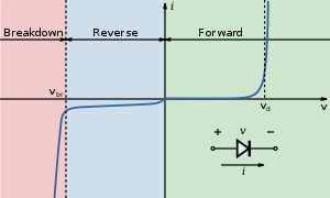
The LED consists of a chip of semiconducting material doped with impurities to create a p-n junction. As in other diodes, current flows easily from the p-side, or anode, to the n-side, or cathode, but not in the reverse direction. Charge-carriers—electrons and holes—flow into the junction from electrodes with different voltages. When an electron meets a hole, it falls into a lower energy level and releases energy in the form of a photon.
The wavelength of the light emitted, and thus its color, depends on the band gap energy of the materials forming the p-n junction. In silicon or germanium diodes, the electrons and holes usually recombine by a non-radiative transition, which produces no optical emission, because these are indirect band gap materials. The materials used for the LED have a direct band gap with energies corresponding to near-infrared, visible, or near-ultraviolet light.
LED development began with infrared and red devices made with gallium arsenide. Advances in materials science have enabled making devices with ever-shorter wavelengths, emitting light in a variety of colors.
LEDs are usually built on an n-type substrate, with an electrode attached to the p-type layer deposited on its surface. P-type substrates, while less common, occur as well. Many commercial LEDs, especially GaN/InGaN, also use sapphire substrate.
Most materials used for LED production have very high refractive indices. This means that much light will be reflected back into the material at the material/air surface interface. Thus, light extraction in LEDs is an important aspect of LED production, subject to much research and development.
Refractive index


Bare uncoated semiconductors such as silicon exhibit a very high refractive index relative to open air, which prevents passage of photons arriving at sharp angles relative to the air-contacting surface of the semiconductor. This property affects both the light-emission efficiency of LEDs as well as the light-absorption efficiency of photovoltaic cells. The refractive index of silicon is 3.96 (590 nm),[42] while air is 1.0002926.[43]
In general, a flat-surface uncoated LED semiconductor chip will emit light only perpendicular to the semiconductor’s surface, and a few degrees to the side, in a cone shape referred to as the light cone, cone of light,[44] or the escape cone.[41] The maximum angle of incidence is referred to as the critical angle. When this angle is exceeded, photons no longer escape the semiconductor but are instead reflected internally inside the semiconductor crystal as if it were a mirror.[41]
Internal reflections can escape through other crystalline faces, if the incidence angle is low enough and the crystal is sufficiently transparent to not re-absorb the photon emission. But for a simple square LED with 90-degree angled surfaces on all sides, the faces all act as equal angle mirrors. In this case most of the light can not escape and is lost as waste heat in the crystal.[41]
A convoluted chip surface with angled facets similar to a jewel or fresnel lens can increase light output by allowing light to be emitted perpendicular to the chip surface while far to the sides of the photon emission point.[45]
The ideal shape of a semiconductor with maximum light output would be a microsphere with the photon emission occurring at the exact center, with electrodes penetrating to the center to contact at the emission point. All light rays emanating from the center would be perpendicular to the entire surface of the sphere, resulting in no internal reflections. A hemispherical semiconductor would also work, with the flat back-surface serving as a mirror to back-scattered photons.[46]
All led grow lights are from ledhydroponics.co.uk
all grows are from ledhydroponics customers.
Transition coatings
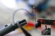
After the doping of the wafer, it is cut apart into individual dies. Each die is commonly called a chip.
Many LED semiconductor chips are encapsulated or potted in clear or colored molded plastic shells. The plastic shell has three purposes:
- Mounting the semiconductor chip in devices is easier to accomplish.
- The tiny fragile electrical wiring is physically supported and protected from damage.
- The plastic acts as a refractive intermediary between the relatively high-index semiconductor and low-index open air.[47]
The third feature helps to boost the light emission from the semiconductor by acting as a diffusing lens, allowing light to be emitted at a much higher angle of incidence from the light cone than the bare chip is able to emit alone.
Efficiency and operational parameters
Typical indicator LEDs are designed to operate with no more than 30–60 milliwatts (mW) of electrical power. Around 1999, Philips Lumileds introduced power LEDs capable of continuous use at one watt. These LEDs used much larger semiconductor die sizes to handle the large power inputs. Also, the semiconductor dies were mounted onto metal slugs to allow for heat removal from the LED die.
One of the key advantages of LED-based lighting sources is high luminous efficacy. White LEDs quickly matched and overtook the efficacy of standard incandescent lighting systems. In 2002, Lumileds made five-watt LEDs available with a luminous efficacy of 18–22 lumens per watt (lm/W). For comparison, a conventional incandescent light bulb of 60–100 watts emits around 15 lm/W, and standard fluorescent lights emit up to 100 lm/W.
As of 2012, the Lumiled catalog gives the following as the best efficacy for each color.[48] The watt-per-watt value is derived using the luminosity function.
| Color | Wavelength range (nm) | Typical efficacy (lm/W) | Typical efficiency (W/W) |
|---|---|---|---|
| Red | 620 < λ < 645 | 72 | 0.39 |
| Red-orange | 610 < λ < 620 | 98 | 0.29 |
| Green | 520 < λ < 550 | 93 | 0.15 |
| Cyan | 490 < λ < 520 | 75 | 0.26 |
| Blue | 460 < λ < 490 | 37 | 0.35 |
In September 2003, a new type of blue LED was demonstrated by the company Cree Inc. to provide 24 mW at 20 milliamperes (mA). This produced a commercially packaged white light giving 65 lm/W at 20 mA, becoming the brightest white LED commercially available at the time, and more than four times as efficient as standard incandescents. In 2006, they demonstrated a prototype with a record white LED luminous efficacy of 131 lm/W at 20 mA. Nichia Corporation has developed a white LED with luminous efficacy of 150 lm/W at a forward current of 20 mA.[49] Cree’s XLamp XM-L LEDs, commercially available in 2011, produce 100 lm/W at their full power of 10 W, and up to 160 lm/W at around 2 W input power. In 2012, Cree announced a white LED giving 254 lm/W,[50] and 303 lm/W in March 2014 .[51] Practical general lighting needs high-power LEDs, of one watt or more. Typical operating currents for such devices begin at 350 mA.
Note that these efficiencies are for the LED chip only, held at low temperature in a lab. Lighting works at higher temperature and with drive circuit losses, so efficiencies are much lower. United States Department of Energy (DOE) testing of commercial LED lamps designed to replace incandescent lamps or CFLs showed that average efficacy was still about 46 lm/W in 2009 (tested performance ranged from 17 lm/W to 79 lm/W).[52]
Efficiency droop
Efficiency droop is the decrease (up to 20%[citation needed]) in luminous efficacy of LEDs as the electrical current increases above tens of milliamps (mA).
This effect, first reported in 1999,[citation needed] was initially theorized to be related to elevated temperatures. Scientists proved the opposite to be true that, although the life of an LED would be shortened, the efficiency droop is less severe at elevated temperatures.[53] The mechanism causing efficiency droop was identified in 2007 as Auger recombination, which was taken with mixed reaction.[54] In 2013, a study conclusively identified Auger recombination as the cause of efficiency droop.[55]
In addition to being less efficient, operating LEDs at higher electrical currents creates higher heat levels which compromise the lifetime of the LED. Because of this increased heating at higher currents, high-brightness LEDs have an industry standard of operating at only 350 mA, which is a compromise between light output, efficiency, and longevity.[54][56][57][58]
Possible solutions
Instead of increasing current levels, luminance is usually increased by combining multiple LEDs in one bulb. Solving the problem of efficiency droop would mean that household LED light bulbs would need fewer LEDs, which would significantly reduce costs.
Researchers at the U.S. Naval Research Laboratory have found a way to lessen the efficiency droop. They found that the droop arises from non-radiative Auger recombination of the injected carriers. They created quantum wells with a soft confinement potential to lessen the non-radiative Auger processes.[59]
Researchers at Taiwan National Central University and Epistar Corp are developing a way to lessen the efficiency droop by using ceramic aluminium nitride (AlN) substrates, which are more thermally conductive than the commercially used sapphire. The higher thermal conductivity reduces self-heating effects.[60]
Lifetime and failure
Solid-state devices such as LEDs are subject to very limited wear and tear if operated at low currents and at low temperatures. Many of the LEDs made in the 1970s and 1980s are still in service in the early 21st century. Typical lifetimes quoted are 25,000 to 100,000 hours, but heat and current settings can extend or shorten this time significantly. [61]
The most common symptom of LED (and diode laser) failure is the gradual lowering of light output and loss of efficiency. Sudden failures, although rare, can also occur. Early red LEDs were notable for their short service life. With the development of high-power LEDs the devices are subjected to higher junction temperatures and higher current densities than traditional devices. This causes stress on the material and may cause early light-output degradation. To quantitatively classify useful lifetime in a standardized manner it has been suggested to use the terms L70 and L50, which is the time it will take a given LED to reach 70% and 50% light output respectively.[62]
LED performance is temperature dependent. Most manufacturers’ published ratings of LEDs are for an operating temperature of 25 °C (77 °F). LEDs used outdoors, such as traffic signals or in-pavement signal lights, and that are utilized in climates where the temperature within the light fixture gets very high, could result in low signal intensities or even failure.[63]
LED light output rises at lower temperatures, leveling off, depending on type, at around −30 °C (−22 °F).[citation needed] Thus, LED technology may be a good replacement in uses such as supermarket freezer lighting[64][65][66] and will last longer than other technologies. Because LEDs emit less heat than incandescent bulbs, they are an energy-efficient technology for uses such as in freezers and refrigerators. However, because they emit little heat, ice and snow may build up on the LED light fixture in colder climates.[63] Similarly, this lack of waste heat generation has been observed to sometimes cause significant problems with street traffic signals and airport runway lighting in snow-prone areas. In response to this problem, some LED lighting systems have been designed with an added heating circuit at the expense of reduced overall electrical efficiency of the system; additionally, research has been done to develop heat sink technologies that will transfer heat produced within the junction to appropriate areas of the light fixture.[67]
Colors and materials
Conventional LEDs are made from a variety of inorganic semiconductor materials. The following table shows the available colors with wavelength range, voltage drop and material:
| Color | Wavelength [nm] | Voltage drop [ΔV] | Semiconductor material |
|---|---|---|---|
| Infrared | λ > 760 | ΔV < 1.63 | Gallium arsenide (GaAs) Aluminium gallium arsenide (AlGaAs) |
| Red | 610 < λ < 760 | 1.63 < ΔV < 2.03 | Aluminium gallium arsenide (AlGaAs) Gallium arsenide phosphide (GaAsP) Aluminium gallium indium phosphide (AlGaInP) Gallium(III) phosphide (GaP) |
| Orange | 590 < λ < 610 | 2.03 < ΔV < 2.10 | Gallium arsenide phosphide (GaAsP) Aluminium gallium indium phosphide (AlGaInP) Gallium(III) phosphide (GaP) |
| Yellow | 570 < λ < 590 | 2.10 < ΔV < 2.18 | Gallium arsenide phosphide (GaAsP) Aluminium gallium indium phosphide (AlGaInP) Gallium(III) phosphide (GaP) |
| Green | 500 < λ < 570 | 1.9[68] < ΔV < 4.0 | Traditional green: Gallium(III) phosphide (GaP) Aluminium gallium indium phosphide (AlGaInP) Aluminium gallium phosphide (AlGaP) Pure green: Indium gallium nitride (InGaN) / Gallium(III) nitride (GaN) |
| Blue | 450 < λ < 500 | 2.48 < ΔV < 3.7 | Zinc selenide (ZnSe) Indium gallium nitride (InGaN) Silicon carbide (SiC) as substrate Silicon (Si) as substrate—under development |
| Violet | 400 < λ < 450 | 2.76 < ΔV < 4.0 | Indium gallium nitride (InGaN) |
| Purple | Multiple types | 2.48 < ΔV < 3.7 | Dual blue/red LEDs, blue with red phosphor, or white with purple plastic |
| Ultraviolet | λ < 400 | 3.1 < ΔV < 4.4 | Diamond (235 nm)[69] Boron nitride (215 nm)[70][71] Aluminium nitride (AlN) (210 nm)[72] Aluminium gallium nitride (AlGaN) Aluminium gallium indium nitride (AlGaInN)—down to 210 nm[73] |
| Pink | Multiple types | ΔV ~ 3.3[74] | Blue with one or two phosphor layers: yellow with red, orange or pink phosphor added afterwards, or white phosphors with pink pigment or dye over top.[75] |
| White | Broad spectrum | ΔV = 3.5 | Blue/UV diode with yellow phosphor |
RGB
RGB LEDs consist of three LEDs. Each LED actually has one red, one green and one blue light. These three colored LEDs are capable of producing any color.

Ultraviolet and blue LEDs

Current bright blue LEDs are based on the wide band gap between semiconductors GaN (gallium nitride) and InGaN (indium gallium nitride). They can be added to existing red and green LEDs to produce the impression of white light. Modules combining the three colors are used in big video screens and in adjustable-color fixtures.
The first blue-violet LED using magnesium-doped gallium nitride was made at Stanford University in 1972 by Herb Maruska and Wally Rhines, doctoral students in materials science and engineering.[76][77] At the time Maruska was on leave from RCA Laboratories, where he collaborated with Jacques Pankove on related work. In 1971, the year after Maruska left for Stanford, his RCA colleagues Pankove and Ed Miller demonstrated the first blue electroluminescence from zinc-doped gallium nitride, though the subsequent device Pankove and Miller built, the first actual gallium nitride light-emitting diode, emitted green light.[78][79] In 1974 the U.S. patent office awarded Maruska, Rhines and Stanford professor David Stevenson a patent for their work in 1972 (U.S. Patent US3819974 A) and today magnesium-doping of gallium nitride continues to be the basis for all commercial blue LEDs and laser diodes. These devices built in the early 1970s had too little light output to be of practical use and research into gallium nitride devices slowed. In August 1989, Cree Inc. introduced the first commercially available blue LED based on the indirect bandgap semiconductor, silicon carbide.[80] SiC LEDs had very low efficiency, no more than about 0.03%, but did emit in the blue portion of the visible light spectrum.
In the late 1980s, key breakthroughs in GaN epitaxial growth and p-type doping[81] ushered in the modern era of GaN-based optoelectronic devices. Building upon this foundation, in 1993 high-brightness blue LEDs were demonstrated.[82] High-brightness blue LEDs invented by Shuji Nakamura of Nichia Corporation using gallium nitride revolutionized LED lighting, making high-power light sources practical.
Nakamura was awarded the 2006 Millennium Technology Prize for his invention.[83] Nakamura, Hiroshi Amano and Isamu Akasaki were awarded the Nobel Prize in Physics in 2014 for the invention of the blue LED.[84][85][86]
By the late 1990s, blue LEDs became widely available. They have an active region consisting of one or more InGaN quantum wells sandwiched between thicker layers of GaN, called cladding layers. By varying the relative In/Ga fraction in the InGaN quantum wells, the light emission can in theory be varied from violet to amber. Aluminium gallium nitride (AlGaN) of varying Al/Ga fraction can be used to manufacture the cladding and quantum well layers for ultraviolet LEDs, but these devices have not yet reached the level of efficiency and technological maturity of InGaN/GaN blue/green devices. If un-alloyed GaN is used in this case to form the active quantum well layers, the device will emit near-ultraviolet light with a peak wavelength centred around 365 nm. Green LEDs manufactured from the InGaN/GaN system are far more efficient and brighter than green LEDs produced with non-nitride material systems, but practical devices still exhibit efficiency too low for high-brightness applications.
With nitrides containing aluminium, most often AlGaN and AlGaInN, even shorter wavelengths are achievable. Ultraviolet LEDs in a range of wavelengths are becoming available on the market. Near-UV emitters at wavelengths around 375–395 nm are already cheap and often encountered, for example, as black light lamp replacements for inspection of anti-counterfeiting UV watermarks in some documents and paper currencies. Shorter-wavelength diodes, while substantially more expensive, are commercially available for wavelengths down to 240 nm.[87] As the photosensitivity of microorganisms approximately matches the absorption spectrum of DNA, with a peak at about 260 nm, UV LED emitting at 250–270 nm are to be expected in prospective disinfection and sterilization devices. Recent research has shown that commercially available UVA LEDs (365 nm) are already effective disinfection and sterilization devices.[88]
Deep-UV wavelengths were obtained in laboratories using aluminium nitride (210 nm),[72] boron nitride (215 nm)[70][71] and diamond (235 nm).[69]
White light
There are two primary ways of producing white light-emitting diodes (WLEDs), LEDs that generate high-intensity white light. One is to use individual LEDs that emit three primary colors[89]—red, green, and blue—and then mix all the colors to form white light. The other is to use a phosphor material to convert monochromatic light from a blue or UV LED to broad-spectrum white light, much in the same way a fluorescent light bulb works.
There are three main methods of mixing colors to produce white light from an LED:
- blue LED + green LED + red LED (color mixing; can be used as backlighting for displays)
- near-UV or UV LED + RGB phosphor (an LED producing light with a wavelength shorter than blue’s is used to excite an RGB phosphor)
- blue LED + yellow phosphor (two complementary colors combine to form white light; more efficient than first two methods and more commonly used)[90]
Because of metamerism, it is possible to have quite different spectra that appear white. However, the appearance of objects illuminated by that light may vary as the spectrum varies.
RGB systems


White light can be formed by mixing differently colored lights; the most common method is to use red, green, and blue (RGB). Hence the method is called multi-color white LEDs (sometimes referred to as RGB LEDs). Because these need electronic circuits to control the blending and diffusion of different colors, and because the individual color LEDs typically have slightly different emission patterns (leading to variation of the color depending on direction) even if they are made as a single unit, these are seldom used to produce white lighting. Nevertheless, this method is particularly interesting in many uses because of the flexibility of mixing different colors,[91] and, in principle, this mechanism also has higher quantum efficiency in producing white light.
There are several types of multi-color white LEDs: di-, tri-, and tetrachromatic white LEDs. Several key factors that play among these different methods, include color stability, color rendering capability, and luminous efficacy. Often, higher efficiency will mean lower color rendering, presenting a trade-off between the luminous efficiency and color rendering. For example, the dichromatic white LEDs have the best luminous efficacy (120 lm/W), but the lowest color rendering capability. However, although tetrachromatic white LEDs have excellent color rendering capability, they often have poor luminous efficiency. Trichromatic white LEDs are in between, having both good luminous efficacy (>70 lm/W) and fair color rendering capability.
One of the challenges is the development of more efficient green LEDs. The theoretical maximum for green LEDs is 683 lumens per watt but as of 2010 few green LEDs exceed even 100 lumens per watt. The blue and red LEDs get closer to their theoretical limits.
Multi-color LEDs offer not merely another means to form white light but a new means to form light of different colors. Most perceivable colors can be formed by mixing different amounts of three primary colors. This allows precise dynamic color control. As more effort is devoted to investigating this method, multi-color LEDs should have profound influence on the fundamental method that we use to produce and control light color. However, before this type of LED can play a role on the market, several technical problems must be solved. These include that this type of LED’s emission power decays exponentially with rising temperature,[92] resulting in a substantial change in color stability. Such problems inhibit and may preclude industrial use. Thus, many new package designs aimed at solving this problem have been proposed and their results are now being reproduced by researchers and scientists.
Correlated color temperature (CCT) dimming for LED technology is regarded as a difficult task, since binning, age and temperature drift effects of LEDs change the actual color value output. Feedback loop systems are used for example with color sensors, to actively monitor and control the color output of multiple color mixing LEDs.[93]
Phosphor-based LEDs

This method involves coating LEDs of one color (mostly blue LEDs made of InGaN) with phosphors of different colors to form white light; the resultant LEDs are called phosphor-based or phosphor-converted white LEDs (pcLEDs).[94] A fraction of the blue light undergoes the Stokes shift being transformed from shorter wavelengths to longer. Depending on the color of the original LED, phosphors of different colors can be employed. If several phosphor layers of distinct colors are applied, the emitted spectrum is broadened, effectively raising the color rendering index (CRI) value of a given LED.[95]
Phosphor-based LED efficiency losses are due to the heat loss from the Stokes shift and also other phosphor-related degradation issues. Their luminous efficacies compared to normal LEDs depend on the spectral distribution of the resultant light output and the original wavelength of the LED itself. For example, the luminous efficacy of a typical YAG yellow phosphor based white LED ranges from 3 to 5 times the luminous efficacy of the original blue LED because of the human eye’s greater sensitivity to yellow than to blue (as modeled in the luminosity function). Due to the simplicity of manufacturing the phosphor method is still the most popular method for making high-intensity white LEDs. The design and production of a light source or light fixture using a monochrome emitter with phosphor conversion is simpler and cheaper than a complex RGB system, and the majority of high-intensity white LEDs presently on the market are manufactured using phosphor light conversion.
Among the challenges being faced to improve the efficiency of LED-based white light sources is the development of more efficient phosphors. As of 2010, the most efficient yellow phosphor is still the YAG phosphor, with less than 10% Stoke shift loss. Losses attributable to internal optical losses due to re-absorption in the LED chip and in the LED packaging itself account typically for another 10% to 30% of efficiency loss. Currently, in the area of phosphor LED development, much effort is being spent on optimizing these devices to higher light output and higher operation temperatures. For instance, the efficiency can be raised by adapting better package design or by using a more suitable type of phosphor. Conformal coating process is frequently used to address the issue of varying phosphor thickness.
Some phosphor-based white LEDs encapsulate InGaN blue LEDs inside phosphor-coated epoxy. Alternatively, the LED might be paired with a remote phosphor, a preformed polycarbonate piece coated with the phosphor material. Remote phosphors provide more diffuse light, which is desirable for many applications. Remote phosphor designs are also more tolerant of variations in the LED emissions spectrum. A common yellow phosphor material is cerium-doped yttrium aluminium garnet (Ce3+:YAG).
White LEDs can also be made by coating near-ultraviolet (NUV) LEDs with a mixture of high-efficiency europium-based phosphors that emit red and blue, plus copper and aluminium-doped zinc sulfide (ZnS:Cu, Al) that emits green. This is a method analogous to the way fluorescent lamps work. This method is less efficient than blue LEDs with YAG:Ce phosphor, as the Stokes shift is larger, so more energy is converted to heat, but yields light with better spectral characteristics, which render color better. Due to the higher radiative output of the ultraviolet LEDs than of the blue ones, both methods offer comparable brightness. A concern is that UV light may leak from a malfunctioning light source and cause harm to human eyes or skin.
Other white LEDs
Another method used to produce experimental white light LEDs used no phosphors at all and was based on homoepitaxially grown zinc selenide (ZnSe) on a ZnSe substrate that simultaneously emitted blue light from its active region and yellow light from the substrate.[96]
A new style of wafers composed of gallium-nitride-on-silicon (GaN-on-Si) is being used to produce white LEDs using 200-mm silicon wafers. This avoids the typical costly sapphire substrates in relatively small 100- or 150-mm wafer sizes.[97] It is predicted that by 2020, 40% of all GaN LEDs will be made with GaN-on-Si. Manufacturing large sapphire material is difficult, while large silicon material is cheaper and more abundant. LED companies shifting from using sapphire to silicon should be a minimal investment.[98]
Organic light-emitting diodes (OLEDs)


All led grow lights are from ledhydroponics.co.uk
all grows are from ledhydroponics customers.
In an organic light-emitting diode (OLED), the electroluminescent material comprising the emissive layer of the diode is an organic compound. The organic material is electrically conductive due to the delocalization of pi electrons caused by conjugation over all or part of the molecule, and the material therefore functions as an organic semiconductor.[99] The organic materials can be small organic molecules in a crystalline phase, or polymers.
The potential advantages of OLEDs include thin, low-cost displays with a low driving voltage, wide viewing angle, and high contrast and color gamut.[100] Polymer LEDs have the added benefit of printable[101][102] and flexible[103] displays. OLEDs have been used to make visual displays for portable electronic devices such as cellphones, digital cameras, and MP3 players while possible future uses include lighting and televisions.[100]
Quantum dot LEDs
Quantum dots (QD) are semiconductor nanocrystals that possess unique optical properties.[104] Their emission color can be tuned from the visible throughout the infrared spectrum. This allows quantum dot LEDs to create almost any color on the CIE diagram. This provides more color options and better color rendering than white LEDs since the emission spectra is much narrower, characteristic of quantum confined states. There are two types of schemes for QD excitation. One uses photo excitation with a primary light source LED (typically blue or UV LEDs are used). The other is direct electrical excitation first demonstrated by Alivisatos et al.[105]
One example of the photo-excitation scheme is a method developed by Michael Bowers, at Vanderbilt University in Nashville, involving coating a blue LED with quantum dots that glow white in response to the blue light from the LED. This method emits a warm, yellowish-white light similar to that made by incandescent bulbs.[106] Quantum dots are also being considered for use in white light-emitting diodes in liquid crystal display (LCD) televisions.[107]
In February 2011 scientists at PlasmaChem GmbH could synthesize quantum dots for LED applications and build a light converter on their basis, which could efficiently convert light from blue to any other color for many hundred hours.[108] Such QDs can be used to emit visible or near infrared light of any wavelength being excited by light with a shorter wavelength.
The structure of QD-LEDs used for the electrical-excitation scheme is similar to basic design of OLED. A layer of quantum dots is sandwiched between layers of electron-transporting and hole-transporting materials. An applied electric field causes electrons and holes to move into the quantum dot layer and recombine forming an exciton that excites a QD. This scheme is commonly studied for quantum dot display. The tunability of emission wavelengths and narrow bandwidth is also beneficial as excitation sources for fluorescence imaging. Fluorescence near-field scanning optical microscopy (NSOM) utilizing an integrated QD-LED has been demonstrated.[109]
In February 2008, a luminous efficacy of 300 lumens of visible light per watt of radiation (not per electrical watt) and warm-light emission was achieved by using nanocrystals.[110]
Types
The main types of LEDs are miniature, high-power devices and custom designs such as alphanumeric or multi-color.[111]
Miniature


These are mostly single-die LEDs used as indicators, and they come in various sizes from 2 mm to 8 mm, through-hole and surface mount packages. They usually do not use a separate heat sink.[112] Typical current ratings ranges from around 1 mA to above 20 mA. The small size sets a natural upper boundary on power consumption due to heat caused by the high current density and need for a heat sink.
Common package shapes include round, with a domed or flat top, rectangular with a flat top (as used in bar-graph displays), and triangular or square with a flat top. The encapsulation may also be clear or tinted to improve contrast and viewing angle.
Researchers at the University of Washington have invented the thinnest LED. It is made of two-dimensional (2-D) flexible materials. It is 3 atoms thick, which is 10 to 20 times thinner than three-dimensional (3-D) LEDs and is also 10,000 times smaller than the thickness of a human hair. These 2-D LEDs are going to make it possible to create smaller, more energy-efficient lighting, optical communication and nano lasers.[113]
There are three main categories of miniature single die LEDs:
- Low-current: typically rated for 2 mA at around 2 V (approximately 4 mW consumption).
- Standard: 20 mA LEDs (ranging from approximately 40 mW to 90 mW) at around:
-
- 1.9 to 2.1 V for red, orange and yellow,
- 3.0 to 3.4 V for green and blue,
- 2.9 to 4.2 V for violet, pink, purple and white.
- Ultra-high-output: 20 mA at approximately 2 V or 4–5 V, designed for viewing in direct sunlight.
5 V and 12 V LEDs are ordinary miniature LEDs that incorporate a suitable series resistor for direct connection to a 5 V or 12 V supply.
Mid-range
Medium-power LEDs are often through-hole-mounted and mostly utilized when an output of just tens of lumens are needed. They sometimes have the diode mounted to four leads (two cathode leads, two anode leads) for better heat conduction and carry an integrated lens. An example of this is the Superflux package, from Philips Lumileds. These LEDs are most commonly used in light panels, emergency lighting, and automotive tail-lights. Due to the larger amount of metal in the LED, they are able to handle higher currents (around 100 mA). The higher current allows for the higher light output required for tail-lights and emergency lighting.
High-power

High-power LEDs (HPLEDs) or high-output LEDs (HO-LEDs) can be driven at currents from hundreds of mA to more than an ampere, compared with the tens of mA for other LEDs. Some can emit over a thousand lumens.[114][115] LED power densities up to 300 W/cm2 have been achieved.[116] Since overheating is destructive, the HPLEDs must be mounted on a heat sink to allow for heat dissipation. If the heat from a HPLED is not removed, the device will fail in seconds. One HPLED can often replace an incandescent bulb in a flashlight, or be set in an array to form a powerful LED lamp.
Some well-known HPLEDs in this category are the Nichia 19 series, Lumileds Rebel Led, Osram Opto Semiconductors Golden Dragon, and Cree X-lamp. As of September 2009, some HPLEDs manufactured by Cree Inc. now exceed 105 lm/W[117] (e.g. the XLamp XP-G LED chip emitting Cool White light) and are being sold in lamps intended to replace incandescent, halogen, and even fluorescent lights, as LEDs grow more cost competitive.
The impact of Haitz’s law which describes the exponential rise in light output of LEDs over time can be readily seen in year over year increases in lumen output and efficiency. For example, the CREE XP-G series LED achieved 105 lm/W in 2009,[117] while Nichia released the 19 series with a typical efficacy of 140 lm/W in 2010.[118]
AC driven LED
LEDs have been developed by Seoul Semiconductor that can operate on AC power without the need for a DC converter. For each half-cycle, part of the LED emits light and part is dark, and this is reversed during the next half-cycle. The efficacy of this type of HPLED is typically 40 lm/W.[119] A large number of LED elements in series may be able to operate directly from line voltage. In 2009, Seoul Semiconductor released a high DC voltage LED, named as ‘Acrich MJT’, capable of being driven from AC power with a simple controlling circuit. The low-power dissipation of these LEDs affords them more flexibility than the original AC LED design.[120]
Application-specific variations
Flashing
Used as attention seeking indicators without requiring external electronics. Flashing LEDs resemble standard LEDs but they contain an integrated multivibrator circuit that causes the LED to flash with a typical period of one second. In diffused lens LEDs this is visible as a small black dot. Most flashing LEDs emit light of one color, but more sophisticated devices can flash between multiple colors and even fade through a color sequence using RGB color mixing.
Bi-color LED
Two different LED emitters in one case. There are two types of these. One type consists of two dies connected to the same two leads antiparallel to each other. Current flow in one direction emits one color, and current in the opposite direction emits the other color. The other type consists of two dies with separate leads for both dies and another lead for common anode or cathode, so that they can be controlled independently.

Tri-color
Three different LED emitters in one case. Each emitter is connected to a separate lead so they can be controlled independently. A four-lead arrangement is typical with one common lead (anode or cathode) and an additional lead for each color.
RGB
Tri-color LEDs with red, green, and blue emitters, in general using a four-wire connection with one common lead (anode or cathode). These LEDs can have either common positive or common negative leads. Others however, have only two leads (positive and negative) and have a built in tiny electronic control unit.
Decorative multicolor
Incorporates several emitters of different colors supplied by only two lead-out wires. Colors are switched internally simply by varying the supply voltage. (In a cheap ‘Melinera’ garden lamp supplied by OWIM GmbH & Co KG in 2013 the LEDs are within a clear casting of 5mm diameter, 10mm long which encapsulates 3 LEDs which change between red, green and blue as the DC supply varies between about 2 volts and 3 volts).
Alphanumeric
Available in seven-segment, starburst and dot-matrix format. Seven-segment displays handle all numbers and a limited set of letters. Starburst displays can display all letters. Dot-matrix displays typically use 5×7 pixels per character. Seven-segment LED displays were in widespread use in the 1970s and 1980s, but rising use of liquid crystal displays, with their lower power needs and greater display flexibility, has reduced the popularity of numeric and alphanumeric LED displays.
Digital RGB
These are RGB LEDs that contain their own “smart” control electronics. In addition to power and ground, these provide connections for data in, data out, and sometimes a clock or strobe signal. These are connected in a daisy chain, with the data in of the first LED sourced by a microprocessor, which can control the brightness and color of each LED independently of the others. They are used where a combination of maximum control and minimum visible electronics are needed such as strings for Christmas and LED matrices, few even have refresh rates in the kHz range allowing for basic video applications
All led grow lights are from ledhydroponics.co.uk
all grows are from ledhydroponics customers.
LED Application Notes – LED Basics
Eye Protection – LEDs are very bright. DO NOT look directly into the LED light. The light can be intense enough to injure human eyes.
- Technical Index

How does a LED work?
This is a very simple explanation of the construction and function of LEDs. White LEDs need 3.6VDC and use approximately 30 milliamps of current, a power dissipation of 100 milliwatts. The positive power is applied to one side of the LED semiconductor through a lead (1 anode) and a whisker (4). The other side of the semiconductor is attached to the top of the anvil (7) that is the negative power lead (2 cathode). It is the chemical makeup of the LED semiconductor (6) that determines the color of the light the LED produces. The epoxy resin enclosure (3 and 5) has three functions. It is designed to allow the most light to escape from the semiconductor, it focuses the light (view angle), and it protects the LED semiconductor from the elements. As you can see, the entire unit is totally embedded in epoxy. This is what make LEDs virtually indestructible. There are no loose or moving parts within the solid epoxy enclosure.
Therefore, a light-emitting diode (LED) is essentially a PN junction semiconductor diode that emits light when current is applied. By definition, it is a solid-state device that controls current without heated filaments and is therefore very reliable. LED performance is based on a few primary characteristics:

LED Colors
LEDs are highly monochromatic, emitting a pure color in a narrow frequency range. The color emitted from an LED is identified by peak wavelength (lpk) and measured in nanometers (nm ).
Peak wavelength is a function of the LED chip material. Although process variations are ±10 NM, the 565 to 600 NM wavelength spectral region is where the sensitivity level of the human eye is highest. Therefore, it is easier to perceive color variations in yellow and amber LEDs than other colors.
LEDs are made from gallium-based crystals that contain one or more additional materials such as phosphorous to produce a distinct color. Different LED chip technologies emit light in specific regions of the visible light spectrum and produce different intensity levels
Comparison of chip technologies for wide-angle, non-diffused LEDs
|
LED |
Standard Brightness | High Brightness | ||||||
| Chip Material |
lpk (NM) |
Iv (mcd) |
Viewing Angle |
Chip Material |
lpk (NM) |
Iv3 (mcd) |
Viewing Angle |
|
|
Red |
GaAsP/GaP |
635 |
120 |
35 |
AS AlInGaP |
635 |
900 |
30 |
|
Orange |
GaAsP/Gap |
605 |
90 |
30 |
AS AlInGaP |
609 |
1,300 |
30 |
|
Amber |
GaAsP/Gap |
583 |
100 |
35 |
AS AlInGaP |
592 |
1,300 |
30 |
|
Yellow |
Gap |
570 |
160 |
30 |
— |
— |
— |
— |
|
Green |
Gap |
565 |
140 |
24 |
GaN |
520 |
1,200 |
45 |
|
Turquoise |
— |
— |
— |
— |
GaN |
495 |
2,000 |
30 |
|
Blue |
— |
— |
— |
— |
GaN |
465 |
325 |
45 |
White LED Light
When light from all parts of the visible spectrum overlap one another, the additive mixture of colors appears white. However, the eye does not require a mixture of all the colors of the spectrum to perceive white light. Primary colors from the upper, middle, and lower parts of the spectrum (red, green, and blue), when combined, appear white. To achieve this combination with LEDs requires a sophisticated electro-optical design to control the blend and diffusion of colors. Variations in LED color and intensity further complicate this process.
Presently it is possible to produce white light with a single LED using a phosphor layer (Yttrium Aluminum Garnet) on the surface of a blue (Gallium Nitride) chip. Although this technology produces various hues, white LEDs may be appropriate to illuminate opaque lenses or backlight legends. However, using colored LEDs to illuminate similarly colored lenses produces better visibility and overall appearance.

Intensity
LED light output varies with the type of chip, encapsulation, efficiency of individual wafer lots and other variables. Several LED manufacturers use terms such as “super-bright,” and “ultra-bright” to describe LED intensity. Such terminology is entirely subjective, as there is no industry standard for LED brightness. The amount of light emitted from an LED is quantified by a single point, on-axis luminous intensity value (Iv). LED intensity is specified in terms of millicandela (mcd). This on-axis measurement is not comparable to mean spherical candlepower (MSCP) values used to quantify the light produced by incandescent lamps.
Luminous intensity
is roughly proportional to the amount of current (If) supplied to the LED. The greater the current, the higher the intensity. Of course, there are design limits. Generally, LEDs are designed to operate at 20 milliamps (mA). However, operating current must be reduced relative to the amount of heat in the application. For example, 6-chip LEDs produce more heat than single-chip LEDs. 6-chip LEDs incorporate multiple wire bonds and junction points that are affected more by thermal stress than single-chip LEDs. Similarly, LEDs designed to operate at higher design voltages are subject to greater heat. LEDs are designed to provide long-life operation because of optimal design currents considering heat dissipation and other degradation factors.
Eye Safety Information
The need to place eye safety labeling on LED products is dependent upon the product design and the application. Only a few LEDs produce sufficient intensity to require eye safety labeling. However, for eye safety, do not stare into the light beam of any LED at close range

Visibility
Luminous intensity (Iv) does not represent the total light output from an LED. Both the luminous intensity and the spatial radiation pattern (viewing angle) must be taken into account. If two LEDs have the same luminous intensity value, the lamp with the larger viewing angle will have the higher total light output.
Theta one-half (q½) is the off-axis angle where the LED’s luminous intensity is half the intensity at direct on-axis view. Two times q½ is the LEDs’ full viewing angle; however, light emission is visible beyond the q½ point. Viewing angles listed in this catalog are identified by their full viewing angle (2q½ °).
LED viewing angle is a function of the LED chip type and the epoxy lens that distributes the light. The highest luminous intensity (mcd rating) does not equate to the highest visibility. The light output from an LED chip is very directional. A higher light output is achieved by concentrating the light in a tight beam. Generally, the higher the mcd rating, the narrower the viewing angle.
The shape of the encapsulation acts as a lens magnifying the light from the LED chip. Additionally, the tint of the encapsulation affects the LED’s visibility. If the encapsulation is diffused, the light emitted by the chip is more dispersed throughout the encapsulation. If the encapsulation is non-diffused or water clear, the light is more intense, but has a narrower viewing angle. Non-diffused and water clear LEDs have identical viewing angles; the only difference is, water clear encapsulations do not have a tint to indicate color when the LED is not illuminated.
Overall visibility can be enhanced by increasing the number of LED chips in the encapsulation, increasing the number of individual LEDs, and utilizing secondary optics to distribute light. To illustrate, consider similar red GaAlAs LED chip technology in four different configurations:

In each case, the amount of visible light depends on how the LED is being viewed. The single chip may be appropriate for direct viewing in competition with high ambient light. The 6-chip may be better suited to backlight a switch or small legend, while the cluster or lensed LED may be best to illuminate a pilot light or larger lens.
Operating Life
Because LEDs are solid-state devices they are not subject to catastrophic failure when operated within design parameters. DDP® LEDs are designed to operate upwards of 50,000 hours at 25°C ambient temperature. Operating life is characterized by the degradation of LED intensity over time. When the LED degrades to half of its original intensity after 50,000 hours it is at the end of its useful life although the LED will continue to operate as output diminishes. Unlike standard incandescent bulbs, DDP® LEDs resist shock and vibration and can be cycled on and off without excessive degradation.
Voltage/Design Current
LEDs are current-driven devices, not voltage driven. Although drive current and light output are directly related, exceeding the maximum current rating will produce excessive heat within the LED chip due to excessive power dissipation. The result will be reduced light output and reduced operating life.
LEDs that are designed to operate at a specific voltage contain a built-in current-limiting resistor. Additional circuitry may include a protection diode for AC operation or full-bridge rectifier for bipolar operation. The operating current for a particular voltage is designed to maintain LED reliability over its operating life.
Precautions While Working With LEDs
General
We cannot assume any responsibility for any accident or damage caused when the products are used beyond the maximum ratings specified herein. These pages are for information only and are the user assumes all responsibility and risk.
The user of these products must confirm the performance of the LEDs after they are actually assembled into the user’s products/systems. It is strongly advised that he user design fail-safe products/systems. We will not be responsible for legal matters which are caused by the malfunction of these products/systems.
Static Electricity and Surge
Static electricity and surge damage LEDs. It is recommended to use a wrist band or anti-electrostatic glove when handling the LEDs. All devices, equipment and machinery must be electrically grounded.
 LEAD Forming:
The leads should be bent at a point at least 3mm from the epoxy resin of the LEDs.
Bending should be performed with the base firmly fixed by means of a jig or radio pliers.


Mounting Method:
The leads should be formed so they are aligned exactly with the holes on the PC board. This will eliminate any stress on the LEDs.
Use LEDs with stoppers or resin spacer to accurately position the LEDs. The epoxy resin base should not be touching the PC board when mounting the LEDs. Mechanical stress to the resin may be caused by the warping of the PC board when soldering. The LEDs must not be designed into a product or system where the epoxy lens is pressed into a plastic or metal board. The lens part of the LED must not be glued onto plastic or metal. The mechanical stress to the leadframe must be minimized.
Soldering
Solder the LEDs no closer than 3mm from the base of the epoxy resin.
For solder dipping, it may be necessary to fix the LEDs for correct positioning. When doing this, any mechanical stress to the LEDs must be avoided.
When soldering, do not apply any mechanical force to the leadframe while heating.
Repositioning after soldering must be avoided.
| Soldering Iron | Dip Soldering | Reflow Soldering | |
|---|---|---|---|
| Lamp LED |
300degC(max), 3sec(max)
|
260degC(max), 5sec(max)
|
Not allowed.
|
| Chip LED |
300degC(max), 3sec(max) with Twin Head iron
|
Not allowed.
|
 |
Cleaning
Avoid exposure to chemicals as they may attack the LED surface and cause discoloration. When washing is required, “isopropyl alcohol” is to be used.
The influence of ultrasonic cleaning on the LEDs differs depending on factors such as oscillator output and the way in which the LEDs are mounted. Therefore, ultrasonic cleaning should only be performed after making certain that it will not cause any damage.
Emission color
LED emission wavelengths vary. LEDs are classified by emission color into different ranks. When a large volume of LEDs are purchased, LEDs with different color ranks will be delivered
Packaging
The leadframes of the LEDs are coated with silver. Care must be taken to maintain a clean storage atmosphere. If the LEDs are exposed to gases such as hydrogen sulfide, it may cause discoloration of the leadframes.
Moistureproof packing is used to keep moisture away from the chip type LEDs. When storing chip type LEDs, please use a sealable package with a moisture absorbent material inside.
LED Cluster Lamp and LED Dot Matrix Unit
Assembly
Please refer to the recommended distance between the leads when designing lead holes on the PC board.
Close attention must be paid on the correct positioning of O-rings and other water proof seals when assembling products/systems.
LEDs are vulnerable to static electricity. When handling the LEDs, necessary precautions regarding static electricity must always be taken into consideration.
Installation of LEDs
Make certain that the lead position and polarity are correct when installing the LEDs.
The interface cable must be as short as possible.
The power supply and ground line must be selected according to their current capacity.
Heat Dissipation
When many LEDs are mounted into a small area, heat generation must be taken into consideration. If there is a possibility that the ambient temperature may exceed 60 degrees centigrade, some kind of forced cooling system will be needed
The ambient operating temperature must be taken into consideration when a product/ system is being designed. There are certain limits to maximum current, at certain temperatures which must be kept in mind.
Handling
When the surface of the LEDs must be cleaned, the LEDs should be wiped softly with detergent. The surface may be damaged and the effect of the lens may be reduced with violent scrubbing.
Others
EMI countermeasures must be taken as a system.
When instantaneous power failure, or a current surge by lightning stops the controller at abnormal conditions, the abnormally high electric current may continue running through the LEDs for an extended period of time. This can damage the LEDs in the system. Circuit protection against abnormally high current must be built into the system to protect against this
Lumens To Watts Conversion Chart
Lumens are the new unit of measurement for light bulbs.
In the past, the strength of light bulbs was measured in watts, which is actually a measure of power. This isn’t a useful unit of measurement for new energy-saving light bulbs, which consume much less power than old-style incandescent light bulbs. So because comparisons based on wattage are no longer meaningful, the strength of new energy-saving light bulbs is expressed in lumens, which measures instead the amount of light they produce. The higher the number of lumens, the brighter the light.
If you haven’t already, you’ll soon start seeing light bulbs categorised by lumens rather than wattage. There isn’t necessarily a correlation between lumens and watts because they measure different things. But as a rough guide, look for:
How many lumens do you need? (240V) |
 |
A person essentially assist to make significantly posts I’d state.
This is the very first time I frequented your website page and thus far?
I amazed with the analysis you made to make this particular publish extraordinary.
Excellent activity!
nice looking lights and very good youtube videos.
thanks mate, check out my facebook https://www.facebook.com/muddyled/
just ask if you need any info.
Would love to forever get updated great web blog!
Keep up the good work.
PPP
Thanks for your kind words, always happy to help and learn.
I really love your website.. Great colors & theme. Did you develop this website yourself?
Please reply back as I?m hoping to create my own blog
and would love to find out where you got this from or exactly what the theme is named.
Cheers!
Thanks mate, i got it guy that do iIT mate.
sorry i cant help. dont know much about doing website
I am actually grateful to the owner of this web page who has shared
this great piece of writing at at this time.
Thanks mate
This article is really cool. I have bookmarked it.
Do you allow guest posting on your blog ?
I can provide high quality posts for you. Let me know.
yes if you posting about led or weed. as long its not spam.
Quality LED
This is the best Led I have seen, it oozes quality. The spectrum is very easy on the eyes, as well as good for the plants. I highly recommend this light to anyone planning to switch to Led. Nice one Muddy, thanks for the great product and excellent service
Thanks Andy always happy to help.
I was just looking at your LED – ledhydroponicsblog site and see that your website has so many good grows, not sure what led to buy.
i have 1.2 x 1.2m tent and i am using 400w sodium. what will be best led to replace my 400w.
my mate has few marshydro led and they dont work, i was going try your led as you got 90 days money back.
thanks in advance for your advice.
hi Cameron
The best led grow lights for your tent will be skyline 800w it only use 400w power and will outdo any 600w HPS.
If you on budget then go for super helios 4 it also only use 400w and you get bigger yield then your present 400w hps.
just email me if you want more info muddy@ledhydroponics.co.uk or you can call me on +447967109663
will give you some discount
i for HPS all the way mate, i never going go with led as i not seen any good grows.
why change something that works.
i use marshydro 300w led in 2013 and i only got 30% of what i normaly get with 600w hps.
led are just bullshit
hi Rebecca
you have to try good quality led. cheap ones are normally not good for growing.
i have 90 days moneyback,
Returns All returns require a Return Merchandise Authorization (RMA). An RMA must be requested within 90 days of the original invoice date or lease date Returns are limited to one(1) product per customer. All items must be returned in “as new” condition in the original packaging and have all accessories. Returns will be charged a 20% restock fee. Shipping charges are non-refundable. When returning product, use a carrier that has tracking capabilities. The customer assumes responsibility for insuring the return shipment and filing the claim for lost or damaged returns. Shipping damage must be reported within a week of receipt of the shipment from translator for non-defective product. Thereafter, all sales are final. 90 day money back guarantee.is for UK customers only.
Hi Rebecca
I used marshydro led and they rubbish for growing but they all over the place, on amazon, ebay and on some other website.
I have tested many and there only 2 that I use budmaster and ledhydroponics.
ledhydroponics are cheaper then budmaster and dose the same on grow.
my tent is 2.4×2.4 and I got 1 budmaster led and 3 x skyline.
I get better yield then when I used 4 x 600w hps , for first time I hade very good grow this summer.
never going back to hps but each to his own mate.
Perfect work you have done, this internet site is really cool its excellent information.
as a new this is so great for me. thanks
Hi Blake
you get good grow with Skyline 400w and it only use 200w power.
or you can go for super Helios 2 and it also use 200w power.
skyline is better and no fan so its silent.
Got skyline 400w 3 months ago and have say i am over the moon with this bit of kit.
Great yield and it was 15% better them my 400w sodium.
Skyline 400 is great led and it only 200w power consumption.
i was not sure how led going work in my grow room there many mix reviews online.
I am going buy 2 more units and cant fault their customer service and next day delivery.